To those of you interested in SCADA systems please have a look at the new SCADA blog.

Tagged with:

This web site was started on December 2004 and now it is one year old. During this year I have tried to find all most of the water simulation packages available.

Judging from the popularity of the posts here EPANET is the most requested item and the DXF2EPA is the most popular tool. Another popular service is the EPANET User-List archive.

I would like to wish all of you a happy new year and all the best 🙂

From CIVIL DESIGNER web page:

Civil Designer is the design system created by civil engineers for civil engineers. Water is a powerful, yet easy to use module for the analysis and extended time simulation of fluid handling networks consisting of pipes, valves, reservoirs and pump stations.

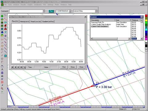
With the Water module you can:

  • Import data from various sources such as ASCII tables, spreadsheets, dBase or MS Access tables as well as DWG/DXF files.
  • Graphical interaction allows you to easily insert nodes and links, make changes to an existing layout by moving a node, change the flow direction, and query or edit a link with a click of the mouse.
  • View the network with a bitmap or cadastral backdrop, or display the site contours and slope shading to decide on optimum network layout.
  • Analyse suburbs separately and combine new and existing models to simulate the complex system of networks that are often found in modern towns and cities. The comprehensive network design will take into account the relationship between different branches.
  • Time-based demand patterns may be defined for different categories of water usage. Each draw-off point may have a different demand pattern.
  • The impact of extensions to the network, increased demand, imposition of water restrictions, power failures, major pipe breaks and empty reservoir conditions may be readily determined.
  • Attach external water consumption tables and compare the measured usage to the modelled consumption to calibrate the demand or identify problem areas in the network.
  • Up to 8 pumps may be handled in each pump station. The pumps are configured in parallel and may be controlled by pressure, water level or be time-based (on/off at certain times).
  • Valves may be controlled manually, by pressure, by flow, or by level. Reservoirs may have any shape ג€” you can select one of the most common shapes or define the water depth versus volume for a particular reservoir.
  • Display the results of an analysis graphically by colour according to calculated results, in tables, or on time-based curves.
  • Generate long sections with the ground profile automatically extracted from the supporting digital terrain model.

For more information see Civil Designer – Water web page.

The WDSA 2006 will hold a special workshop for the Battle of the Water Sensor Network.

The problem description and rules are available at the WDSA 2006 workshops page.

HyperCalc Plus provides a convenient means for converting between English and Metric (SI) units. For example the figure below demonstrates that the ג€œLengthג€ Context provides the functionality to convert between five metric units and nine English units. One meter equals 39.370 or 39 and 3/8 inches. Entering a value on the meter side automatically produces the equivalent inches, and vice versa. There are 13 Contexts for common units. In addition there are two specialty groups of units: ג€œCivil Structuralג€ containing 12 contexts including mass, force, pressure, moments, etc. and ג€œElectricalג€ containing 18 contexts.

HyperCalc Plus also provides forms for ג€œTransportationג€ equations including: Sight Distance, Vertical Curve, Vertical Passing Distance, Horizontal Curve, and Passing Distance. Forms for ג€œDrainageג€ equations include: Continuity, Darcy-Weisbach, Friction Factor, Hazen-Williams, Mannings, Circular Shape Properties, Trapezoid Shape Properties, Rational Formula, and Reynolds Number.

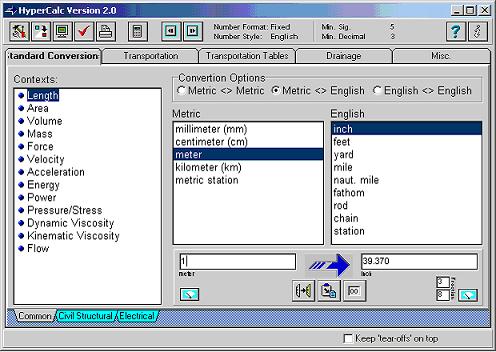
Extensive help files are included. HyperCalc Plus may be downloaded for the web site at:
http://www.utaht2.usu.edu/download.htm

The application was developed at Utah State University as part of a joint project involving Utah State University, the Utah Department of Transportation, and the Federal Highway Administration. It is provided as Free Ware, no registration or licensing fees are required. Professor William Grenney was the Principal Investigator on the project

With WebEPANET you can build an EPANET INP file on the web, run the model, see the map and even see the results.

I’m not sure if anyone will find it useful 🙂

See an example here or try it yourself here.

From Helix Technologies web site:

delta-Q is a powerful tool for engineers and equipment suppliers to quickly and easily design and optimise pipe networks for compressible and incompressible fluids. You can produce economically and technically sound pipe system designs in a very short time. You can calculate friction losses and pressure drop in pipes and fittings for Liquids, Slurries and Gasses. Model complex process flow pipe networks and solve for unknown flow rates and node pressures at the press of a button. Retrieve data from user accessible databases for Liquids, Slurries, Gasses, Pumps, Pipes and Fittings or add your own data.
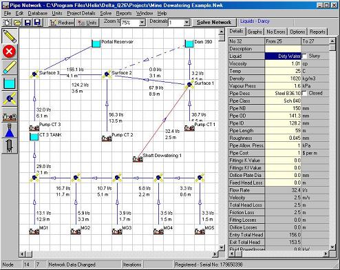
Features:

  • delta-Q includes a CAD DXF file generator for exporting the network diagram to CAD
  • Design and Solve Complex Pipe System Networks.
  • Solves for any number of pipes, nodes and pumps. Uses matrix algebra combined with the Newton-Raphson method for quick, accurate convergence.
  • Drag and Drop Network components onto the screen for quick and easy network creation.
  • Add individual fittings to pipes using the fitting database or enter an estimate of the total K value.
  • Calculate Fitting Losses using the standard K value method or the Kf method which compensates for fluid viscosity and turbulence.
  • Comprehensive Databases for Pipes, Liquids, Slurries, Gasses and Pumps.
  • Setup individual Fluids and properties in each pipe – Model real world process flows with different fluids in the same network.
  • Model what if scenarios – close off certain pipes and view the effects on the network.
  • Display the Network Calculation Results such as Pipe Flows, Velocity, Head Loss, Node Pressure and many others on the Network Diagram.
  • Network Reports Display and Print the Network Pipe and Node Data and Calculation Results in compact Tabular Form.
  • Export the Results to Spreadsheets like MS Excel
  • Click on a Pipe to View the System Curve with the Network Duty Point shown.
  • Perform Complex Orifice Plate Calculations automatically merely by adding an Orifice to a Pipe.
  • Include Networks with unknown pressure nodes and unknown flow nodes or any combination of the two.
  • Model networks containing any number of pumps, reservoirs and spray nozzles and other components.
  • Build a Model to simulate almost any Process Flow condition including pipes, fittings, valves, pumps, orifice plates, vessels, sprinklers, nozzles, columns, flow and pressure control valves.
  • Model any number of pipes, junctions, pumps, vessels, sprinklers, nozzles, tanks, intakes, and outlets as you like in one network.
  • Add individual fittings to each pipe or enter a global K value or Kf value for a quick estimate of fitting losses.
  • You can have different fluids in the same network. For example, you may have a concentrated slurry in one pipe flowing into a junction with a water pipe (or pipes) and dilute slurry flowing through the network from that point onwards.
  • Pipe capital vs. operating costs are calculated to assist you to make decisions on the most economical pipe size for an application.
  • Use any Engineering units you require – it is easy to add your own units, or select Metric, SI or English units supplied with the program.
  • The program is supplied with Sample files and on-line Help to get you started quickly and easily.

For more information see Helix website

Managing Ground-Water Systems
May 22-24, 2006

The MODFLOW conference series has become a tradition for the presentation of cutting-edge practical application of ground water models in all aspects of hydrologic work. MODFLOW, the USGS modular three-dimensional finite-difference, ground-water flow model, has become an international standard for ground-water modeling. MODFLOW serves as a centerpiece for the recurring conference, but we anchor on MODFLOW only because of its widespread use and its status as a community model. The conference organizing committee needs and encourages participation by users of all types of models in all kinds of applications, including those for which MODFLOW is not suitable, so that the modeling capability of our profession will evolve. MODFLOW is a basis from which other models can be considered. The advantages and disadvantages of alternative codes can be reflected from MODFLOW with which nearly all modelers are familiar.

For more details click here.

Process Energy Services is pleased to introduce PUMP & SYSTEMS “BASIC” AND “PRO”, the new software tools created to assist facility operators and engineers optimize existing and new pump systems to improve efficiency and reduce energy costs.

The PUMP & SYSTEMS software tools are designed to take the mystery out of centrifugal pump systems, and help identify opportunities to improve pump efficiency and reduce costs. This program is ideal for modeling water and wastewater pumps, cooling and chilled water system pumps, and process pump systems.

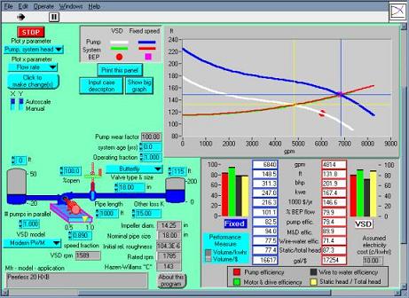
The benefits of PUMP & SYSTEMS software includes:

  • The ability to model an existing pump by inputting pump curve data specifically for the pump being reviewed.
  • Allows the user to evaluate the efficiency of multiple pumps operated in parallel
  • Provides energy cost comparison for operating a pump at full speed or reduced speed with a VSD
  • Evaluates the energy cost impact of the following system changes:
    • Pipe size
    • Pipe length
    • System age
    • Tank levels
    • Fluid temperature
    • Motor efficiency
    • Energy Cost
    • Type of variable speed drive
  • Easy to use pull down menus that allow the user to enter information for pipe sizes, valve types, tank elevations (or static head), motor efficiency, cost of electricity and other parameters to evaluate pump system energy costs.
  • A visual representation of the pump, piping and tank system, a simulated pump curve, and a detailed efficiency comparison list for operating the pump as a fixed speed or variable speed pump (Basic).
  • The ability to model fixed or variable speed multiple pumps operating in parallel to determine system head and flow output as well as the optimum speed and number of pumps to operate the system as efficiently as possible (Pro).

For more information see PUMP & SYSTEMS web page.

MIDUSS is Windows-based software that helps you to engineer complex drainage networks to convey flow hydrographs from single event storms. MIDUSS lets you:

  • generate hydrographs using a variety of built-in hydrologic models
  • design a network of pipes, channels, culverts, ponds, infiltration trenches, cascading pipes, diversions – all with preliminary sizing done automatically and flood routing where appropriate
  • use interactive design and immediate feedback to quickly optimize each element as you progress downstream
  • use automatic mode to analyze and adjust your completed design under more severe storms
  • concentrate on engineering; robust error detection and step-by-step prompts are provided throughout
  • import/export hyetographs or hydrographs at virtually any stage
  • feel good about your investment: we offer competitive software pricing and on-going updates and support
  • get going fast with detailed Reference and Tutorial manuals as well as free audio-visual lessons
  • feel assured we know what we’re doing – MIDUSS is 20 years on the market and still going strong

For more information see MIDUSS web site.